8:02 am

Club Member
July 14, 2016
 Offline
As per John's request on a different thread, I'm posting my winch power interrupt installation on my 04 TJ. John asked to see installation options for both a TJ and a JK. I'm starting a new thread in the fabrication talk section since this is fab work.
I bought the Warn 62132 Power Interrupt Kit which includes the solenoid, battery lead wire, lighted switch, additional wiring and all hardware. The battery lead is 18" long so the solenoid needs to be installed close to the battery. This makes sense since the reason for this safety feature is to eliminate the long, hot lead wire that goes from the battery directly to the front bumper mounted winch. While the switch quality isn't the best, I do like the fact that it is a lighted switch when the switch is in the on position (i.e. winch power on) and not illuminated when the power to the winch is off. Since it is a toggle switch with no on or off indicator, the light is the only way to tell if the winch power is on or off.
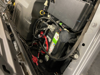
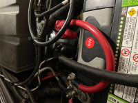
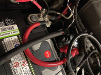
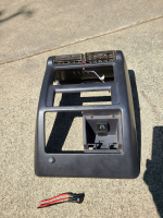
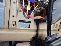
I mounted the solenoid in about the only place I could find to mount it on my TJ. I mounted it on the inside of the passenger side fender well. The other option was to mount it on the firewall close to the battery but I had no real space on the firewall due to other aftermarket wires being in the way. I mounted the switch at the bottom of the dash on the passenger side, making sure the location didn't interfere with future removal the bezel for the radio and heater. I created a "Winch Power" label in case someone else needed to operate my winch without me being there. I rerouted the red winch wire between the air filter box and the fuse box, which worked perfectly. I tied the red wire for the lighted switch into the radio red power wire so that it is connected to a key activated wire and not on unless the Jeep's key is in the on position. The switch has a ground wire that I mounted to a metal bracket behind the glove box with self tapping screw. The yellow wire runs from the solenoid to the in cab switch and is the only wire that needs to penetrate the firewall. There is a green ground wire from the solenoid to negative terminal on the battery.
Note: in the pictures below the red starter wire passes next to the solenoid going from the starter to the battery. The picture may be deceiving because it looks like this wire is going to the solenoid, which it isn't. Additional note: to the left of the shifter on the lower dash is where I mounted my switches long ago for my bumper and A pillar mounted light bars. I also labeled them to indicate which switch is for which light bar. They are tri position switches because I have a white and amber light option.
8:54 am

Club Webmaster
August 5, 2017
 Offline
9:22 am

Club Webmaster
August 5, 2017
 Offline
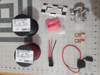
Here is what mine looks like. I would have preferred to mount the solenoid on the other side of the battery on the sheet metal in the rear corner of the engine compartment instead of the plastic battery box, but I have the relays for my 7-point tow harness there (I almost just ripped all that out but I know as soon as I do it i will need to pull a trailer). Some day I would like to upgrade to a dual battery system, at which point it will all be reconfigured anyway. You can see the white and blue wires that run over to the SPod on the other side of the engine compartment. There are no markings on the terminal posts so I expect polarity/flow does not matter, just get the big wires on the big lugs! I also included the parts list I used from amazon, everything not on the list I had on hand already. The solenoid I bought is not the exact one that comes in the Warn kit, looking at the manufacturer's product catalog and some other research I believe it is identical except no warning sticker and hardware bag that comes in the Warn Kit (functionally identical though). The one in the warn kit is 974-1215-011-11 and I am betting only sold to Warn for their kit.
There is an issue with Amazon URLs in the forum I am working on so you cannot click on these, copy them in to your browser to view them.
Solenoid - smile.amazon.com/gp/product/B007W2ND3K/ref=ppx_yo_dt_b_asin_title_o06_s00?ie=UTF8&psc=1
Large Boots - smile.amazon.com/gp/product/B07NBDM76X/ref=ppx_yo_dt_b_asin_title_o05_s00?ie=UTF8&psc=1
Small Boots - smile.amazon.com/gp/product/B01LM2BW6A/ref=ppx_yo_dt_b_asin_title_o04_s00?ie=UTF8&psc=1
Battery Lead - smile.amazon.com/gp/product/B075SK192B/ref=ppx_yo_dt_b_asin_title_o02_s00?ie=UTF8&psc=1
K6NUB
10:45 am

Club Member
July 14, 2016
 Offline
Jamie (K6NUB) said
There are no markings on the terminal posts so I expect polarity/flow does not matter, just get the big wires on the big lugs!
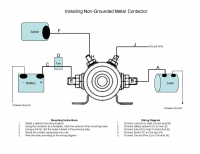
Correct. The Warn instructions say it doesn't matter which of the two larger posts you mount the battery cable and the winch cable to. However, it was very specific as to what wires to mount on the other two posts. The small one on the right was for the switch wire and the small one on the left was for the ground wire. Nice job Jamie!
12:23 pm

Club Member
December 14, 2018
 Offline
The Trombetta solenoid does not come with wiring instructions but there is a BAT stamp on the casing next to the Battery Stud.
The wiring diagram can be found on the company's website.
https://www.trombetta.com/wp-c.....ounded.pdf
Trombetta suggests to add a fuse between the battery lead and the solenoid. I did not do that.
I'm adding a fuse between the switch and solenoid.
1:14 pm

Club Member
July 14, 2016
 Offline
3:14 pm

Club Trailmaster
March 13, 2015
 Offline
Jeff_R said
John, I saw on one forum page where a guy asked why Warn wanted the ground to go directly to the battery. Another guy said he did a chassis ground and it worked just fine. This is what it shows in the diagram you posted (i.e. ground not going to the battery).
Using chassis ground seems like a bad idea to me. Relying on a ground only meant to start the vehicle (150-250 amps) is sketchy compared to the draw of a long winch pull (400-500 amps). Im sure it worked to test and spool and empty winch but seems like a good way to start a fire under the hood of your rig.
4:44 pm

Club Member
December 14, 2018
 Offline
kris_olof said
Jeff_R said
John, I saw on one forum page where a guy asked why Warn wanted the ground to go directly to the battery. Another guy said he did a chassis ground and it worked just fine. This is what it shows in the diagram you posted (i.e. ground not going to the battery).
Using chassis ground seems like a bad idea to me. Relying on a ground only meant to start the vehicle (150-250 amps) is sketchy compared to the draw of a long winch pull (400-500 amps). Im sure it worked to test and spool and empty winch but seems like a good way to start a fire under the hood of your rig.
I can see your point Kris. This is for the small gauge ground wire to activate the solenoid not the ground wire to the winch if that is what you are thinking. The ground wire to the winch is directly connected to the battery. The solenoid only interrupts the positive wire. Trombetta sells a version of this solenoid where the casing is the ground and there is no ground terminal. I apologize if I misinterpreted your response.
Hey I'm no expert and don't want to be responsible for toasting anyone's rig. So when in doubt it is best practice to directly connect to the battery.
4:56 pm

Club Member
July 14, 2016
 Offline
5:20 pm

Club Member
December 14, 2018
 Offline
11:08 pm

Club Member
December 14, 2018
 Offline
Jeff_R said
John, I saw on one forum page where a guy asked why Warn wanted the ground to go directly to the battery. Another guy said he did a chassis ground and it worked just fine. This is what it shows in the diagram you posted (i.e. ground not going to the battery).
Hey Jeff, Be careful of the Trombetta wiring diagram. It looks like yours and Jamie's are wired differently on which post connects to the battery. The Trombetta wiring diagram has the battery connection on the left stud if you placed the solenoid on a table and looking directly at the embossed rings. Interestingly my solenoid has "BAT" stamped on it next to the right stud. This matches the wiring diagram of the Warn kit. The studs for the ground and power from switch match both diagrams.
Does it matter which stud connects to the battery, I don't know.
8:48 am

Club Member
July 14, 2016
 Offline
Sloguy said
Does it matter which stud connects to the battery, I don't know.
Here is what the Warn instructions say:
5. Slip a large plastic boot over the (+) positive cable from the Power Lead or accessory and attach it
to EITHER of the large posts of the Power Interrupt solenoid.
some cut:
6. Slip a large plastic boot over the red 18" Power Interrupt cable and attach the cable to the
remaining large post of the Power Interrupt solenoid. Use the outer nut and washer to secure the cable
end. Push the boot over the solenoid post.
Here is a link to the instructions: https://www.4wd.com/sku/Warn/s....._INS_1.pdf
7:10 pm

Club Member
December 14, 2018
 Offline
Yup, Those are the instructions I read. I just find in funny that the Trombetta diagram says to connect the winch lead to the Stud where it is stamped "BAT" on the solenoid. My Solenoid is a Trombetta. So both those instructions show that it doesn't matter which side is connected to the winch or battery. That is helpful when trying to find a location to mount the solenoid.
1 Guest(s)


